
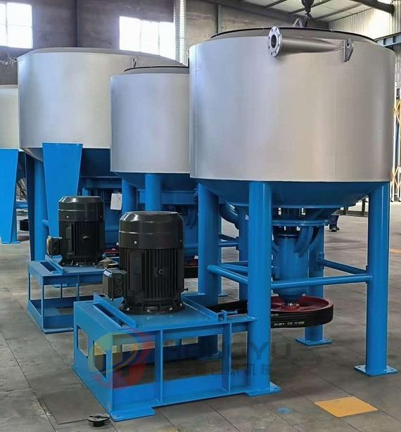
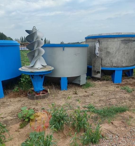
The Hydrapulper is a core pulping device in papermaking lines, primarily used for dissociating waste paper or virgin fiber raw materials into a uniform pulp slurry through hydraulic shearing and mechanical agitation. It is a foundational piece of equipment in both virgin pulp production and recycled waste paper pulping, capable of breaking down raw materials into individual fibers while retaining fiber integrity to ensure the quality of subsequent papermaking processes.
Core Structure & Working Principle
-
Basic Structure
A typical Hydrapulper consists of four key components:
- Tubular tank body: A large, cylindrical or square sealed vessel (usually made of stainless steel or reinforced concrete) that holds the raw materials and water, with a volume ranging from several cubic meters to over 100 cubic meters depending on production scale.
- Impeller rotor: The core working unit, installed at the bottom of the tank, composed of high-strength blades (usually 4–6 blades) driven by a low-speed, high-torque motor. The rotor’s design (such as curved or backward-inclined blades) is optimized to generate strong hydraulic circulation.
- Feed & discharge system: A sealed feed inlet at the top for adding waste paper (or virgin fiber) and water, and a discharge outlet at the bottom or side for transferring the pulped slurry to downstream equipment. Most models are equipped with a reject trap at the tank bottom to capture heavy impurities (e.g., metal scraps, stones) that sink to the bottom, preventing damage to the rotor and subsequent devices.
- Control system: A panel for adjusting water-fiber ratio, rotor speed, and pulping time according to the type of raw material (e.g., old corrugated containers, mixed office waste, or virgin wood chips).
-
Operational Mechanism
The working process of a Hydrapulper relies on the combined action of hydraulic shearing and mechanical agitation:
- First, waste paper (or virgin fiber raw materials) and water are added to the tank in a specific ratio, forming a slurry with an initial consistency of 3%–15% (higher consistency for waste paper recycling to improve fiber recovery).
- When the impeller rotor rotates (usually at 50–150 RPM), it drives the slurry to form a strong circular flow and vortex in the tank. The high-speed fluid creates shearing forces that tear and dissociate paper sheets or fiber bundles into individual fibers. Meanwhile, the rotor blades directly impact and agitate large paper clumps, accelerating the pulping process.
- Heavy impurities (e.g., nails, staples, gravel) in the raw materials sink to the tank bottom and are collected by the reject trap for periodic removal, while lightweight impurities (e.g., plastic films) float to the surface and can be skimmed off manually or via automated devices.
- After a preset pulping time (usually 15–60 minutes depending on raw material type), the fully dissociated pulp slurry is pumped out from the discharge port and sent to subsequent screening, cleaning, or concentration processes.
Key Functions & Application Scenarios
- Raw Material Dissociation: Converts compact paper sheets or fiber raw materials into a uniform fiber slurry, which is a prerequisite for forming paper webs in papermaking. It balances pulping efficiency and fiber protection, avoiding excessive fiber shortening that would reduce paper strength.
- Impurity Classification: Separates heavy, hard impurities from pulp at the pulping stage, reducing the load on downstream purification equipment and protecting precision devices from wear or blockage.
- Adaptability to Diverse Raw Materials: Suitable for both waste paper recycling (OCC, MOW, newsprint) and virgin pulp production (wood chips, bagasse, bamboo fibers), making it a versatile core device in paper mills of all scales.
- Energy-efficient Pulping: The low-speed, high-torque rotor design consumes less energy per unit of pulp compared to high-speed pulping devices, while the closed tank structure reduces noise and fiber loss during operation.
There are no reviews yet.