
Core Structure & Working Principle
-
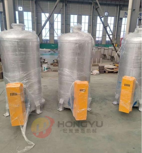
Basic Structure
A typical filtrate tank is constructed from corrosion-resistant materials such as stainless steel, FRP (fiber-reinforced plastic), or coated carbon steel to withstand the mild chemical properties of papermaking filtrate. It includes a sealed tank body, inlet/outlet pipelines, a level monitoring system (e.g., float sensors or ultrasonic gauges), a stirring device (to prevent fiber sedimentation), and a drainage or recycling pump. Some large-scale models also feature a filtration layer or screen to capture residual pulp fibers in the filtrate.
-
Operational Process
Filtrate from dewatering equipment is transported to the tank through dedicated pipelines. Once inside, the tank temporarily stores the liquid, and the stirring system keeps suspended fibers in circulation to avoid clogging pipelines. The level sensor monitors the liquid volume to prevent overflow or dry-running of pumps. Depending on the plant’s process design, the filtrate is either pumped back to the pulp preparation section for reuse (reducing freshwater consumption) or sent to the wastewater treatment system for purification before discharge.
Key Functions & Application Scenarios
- Filtrate Collection & Storage: Centralizes scattered filtrate from multiple dewatering units, ensuring a stable supply for subsequent recycling or treatment.
- Water Resource Recycling: Reuses clean filtrate in pulp dilution and equipment cleaning, cutting down freshwater intake and lowering production costs.
- Fiber Recovery: Traps residual pulp fibers in the filtrate, which can be separated and returned to the pulping process to improve raw material utilization.
- Environmental Protection: Buffers the discharge of filtrate to wastewater systems, preventing sudden surges in flow or pollutant concentration that could disrupt treatment processes.
There are no reviews yet.